
Your child’s favorite electric ride-on car suddenly stopped moving mid-adventure, leaving behind nothing but tears and frustration. You’ve searched for the manufacturer’s wiring diagram but found only confusing tangles of colored wires beneath the seat. Most 12V toy cars from Power Wheels, Peg Perego, and Kid Trax follow predictable wiring patterns that you can decode with basic electrical knowledge. This guide reveals the standard configurations that will help you revive your child’s ride-on without costly professional repairs.
Whether you’re replacing a dead battery, troubleshooting a faulty switch, or upgrading to more powerful components, understanding these wiring fundamentals puts you in control. You’ll learn to identify critical connection points, trace power flow through the system, and safely make modifications that restore hours of playtime. Let’s dive into the electrical heart of your child’s favorite toy.
Locate Critical 12V Toy Car Components
Every electric ride-on car contains the same fundamental electrical system regardless of brand or design. The 12V battery configuration typically consists of either two 6V batteries wired in series or a single 12V sealed lead-acid battery. Power flows from this energy source through protective circuitry to control switches before reaching the drive motors that propel your child forward.
You’ll need to identify these essential elements in your specific model:
- Battery pack (either dual 6V or single 12V configuration)
- Directional control switch that handles forward and reverse operation
- Throttle pedal assembly that regulates speed
- Drive motors (usually one per rear wheel)
- Circuit protection in the form of breakers or fuses
- Charging port for battery replenishment
Find Battery Terminal Connection Points
Battery terminals typically feature either spade connectors that snap on or ring terminals secured with nuts. The positive terminal always appears red while negative connections use black or occasionally white wires. When facing the battery compartment from the rear of the vehicle, manufacturers typically position the positive connection on the right side. Carefully trace each wire from the battery to understand where power initially flows.
Track Motor Wiring Routes Through Chassis
Motor leads run from the rear axle assembly through protective channels in the chassis toward the control switches. These power-carrying wires appear thicker than other wiring in the system, usually red and black in color. Each drive motor connects with two leads—one carrying power (red) and the other serving as the ground return path (black). Follow these wires carefully as they often pass through rubber grommets to prevent chafing against metal edges.
Map Standard 12V Ride-On Circuit Layout
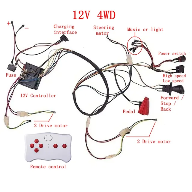
The electrical circuit in most 12V toy cars follows a simple series design that channels power efficiently from source to motors. Current flows from the battery’s positive terminal through the circuit breaker, then to the directional switch. From there, electricity travels to the throttle pedal assembly before completing the circuit through the drive motors back to the battery’s negative terminal.
This essential connection sequence creates a complete electrical pathway:
- Battery positive terminal → circuit breaker
- Circuit breaker → directional switch
- Directional switch → throttle pedal assembly
- Throttle pedal → drive motors
- Drive motors → battery negative terminal
Decode Directional Switch Configurations
Directional switches operate through a clever polarity reversal mechanism. These three-terminal switches position the center terminal as the power input while the outer terminals control motor direction. When you toggle between forward and reverse, the switch physically swaps which motor terminal receives positive versus negative current, changing the rotation direction. This simple yet effective design allows the same motors to propel the vehicle in both directions without additional components.
Recognize Universal Wire Color Standards
Manufacturers maintain consistent color coding across most 12V ride-on models:
- Red: Primary positive power circuit
- Black: Main negative/ground circuit
- White: Secondary ground path (used by some brands)
- Blue: Accessory circuits like horns or sounds
- Yellow: Lighting circuits for headlights
- Green: Signal wires for accessories
This standardization means that once you understand one model’s wiring, you can apply that knowledge to most other 12V ride-on toys.
Trace Power Flow Through Your Ride-On System
Begin your electrical diagnosis at the battery terminals. Set your multimeter to DC voltage and measure across the main terminals—you should see approximately 12.6V on a fully charged battery. Any reading below 11V indicates the battery needs recharging or replacement. No voltage suggests either a completely dead battery or a blown main fuse.
Follow the thick red wire from the battery’s positive terminal to locate the circuit breaker, typically a small rectangular component rated between 30-40 amps. Test voltage on both sides of this breaker; equal readings confirm proper functionality while zero voltage on the output side indicates a tripped or failed breaker that needs resetting or replacement.
Test Directional Switch Functionality
Testing the directional switch requires placing the car in “run” mode. With the multimeter probes on the output terminals, cycle through forward and reverse positions. You should detect 12V on one terminal when in forward gear and on the opposite terminal when in reverse. Absence of voltage in either position signals either switch failure or a wiring break upstream that requires further investigation.
Diagnose Throttle Pedal Circuit Issues
Throttle pedal switches frequently fail due to accumulated dirt or internal corrosion. Disconnect the wiring harness from the pedal assembly and test continuity across the switch terminals while pressing the pedal. A functioning switch shows continuity only when depressed. No continuity when pressed means the switch needs replacement—a common fix that restores operation in many seemingly dead ride-ons.
Fix Common 12V Ride-On Electrical Failures
Complete power loss typically originates from three critical areas: the battery itself, the circuit breaker, or main connection points. Start by verifying battery voltage—below 11V indicates insufficient charge. Next, check the circuit breaker for continuity. Many breakers reset automatically after cooling, while others require manual intervention by pressing a small reset button.
Intermittent operation usually stems from loose connections or failing switches. Perform a “wiggle test” on each connection while the vehicle attempts to operate. Any change in motor behavior during this test indicates a poor connection that needs tightening or replacement.
Repair Motor Wiring Connection Problems
Motor failures manifest as no movement or unusual grinding sounds from the drive train. For accurate diagnosis, disconnect the motor leads and apply 12V power directly to the motor terminals. Functional motors spin freely in both directions when polarity reverses. Non-responsive motors require either internal repair or complete replacement.
Resolve Battery Charging System Faults
Charging issues appear as drastically reduced run times or complete inability to hold a charge. Test your charger’s output voltage—it should measure 14-15V when connected to power but not to the battery. Readings significantly below this range indicate charger failure. Also inspect the charging port for corrosion or bent pins that prevent proper electrical contact during charging sessions.
Upgrade Factory 12V Ride-On Electrical System

Standard 12V systems readily accept several common performance upgrades. Battery upgrades to 15Ah or 18Ah capacity models provide noticeably longer playtime. Ensure any replacement battery fits within the compartment and features identical terminal types and orientation to prevent connection issues.
Motor upgrades to industrial-grade 775-series units dramatically increase speed and torque. These powerful replacements require thicker gauge wiring—upgrade to 12-gauge wire for all high-current applications. Install a 40-50 amp circuit breaker to safely handle the increased electrical load without frequent tripping.
Install Higher Capacity Battery Correctly
Follow these critical steps when upgrading your battery:
- Always disconnect the negative terminal first to prevent short circuits
- Remove the battery hold-down bracket securing the original unit
- Position the new battery with matching terminal orientation
- Upgrade the main fuse to 40 amps to accommodate increased capacity
- Test voltage under load to verify proper installation
Add Custom LED Lighting Circuits
Enhance visibility and fun with LED lighting upgrades by tapping into the existing 12V supply. Wire your lights through a separate switch protected by a 5-amp inline fuse. Connect to the main power circuit after the primary circuit breaker to ensure all accessories remain protected from electrical surges.
Create Your Own Custom Wiring Diagram

Document your vehicle’s specific configuration before making any modifications. Sketch the battery compartment layout with attention to wire colors and connection points. Photograph each wiring junction before disconnection for accurate reassembly reference.
Your custom wiring diagram should include these essential elements:
- Precise battery terminal locations and color coding
- Switch positions and wire routing paths
- Motor connections with wire gauge specifications
- Fuse and breaker ratings with physical locations
Select Proper Wire Gauges for Reliability
Choose wire gauges based on current requirements and run length:
- 12-gauge: Main battery to switch connections (handles high current)
- 14-gauge: Switch to motor circuits
- 16-gauge: Lighting and accessory circuits
- 18-gauge: Signal and low-power circuits
Secure All Electrical Connections Properly
Connection method determines long-term reliability:
- Solder with heat-shrink tubing: Creates permanent, weather-resistant joints
- Quality crimp connectors: Allows for future serviceability
- Weatherproof connectors: Essential for outdoor exposure protection
- Dielectric grease: Prevents corrosion in all connection points
Test Your Complete 12V Ride-On Circuit Safely
Conduct final testing with the rear wheels elevated off the ground to prevent accidental movement. Systematically test each function:
– Directional switching between forward and reverse
– Throttle response throughout the speed range
– Brake operation (if equipped)
– All accessory circuits including lights and sounds
Complete this essential safety checklist before returning the vehicle to your child:
- Verify all connections are tight and properly insulated
- Ensure no wires are pinched or chafing against sharp edges
- Confirm correct fuse ratings are installed throughout the system
- Check that the battery is securely mounted with proper ventilation
Key takeaway: Over 90% of 12V ride-on electrical problems stem from three common failure points: depleted batteries, tripped circuit breakers, and corroded switch contacts. Keep spare fuses, basic tools, and a fully charged spare battery in your repair kit for quick fixes during playtime emergencies. Understanding these fundamental wiring principles transforms you from frustrated parent to household hero who can revive any stalled ride-on car.